
Railway stations and metro networks deploy stretched LCD displays — ultra-wide panels with native aspect ratios far beyond 16:9 — across platforms, carriages, and semi-outdoor transition zones. The stretched form factor is not a design preference; it is a structural response to the physical, safety, and environmental constraints that standard rectangular monitors cannot resolve. This article covers the deployment scenarios, vibration engineering, passenger safety requirements, semi-outdoor brightness specifications, and the energy-saving advantage that local dimming delivers on dark-background rail content.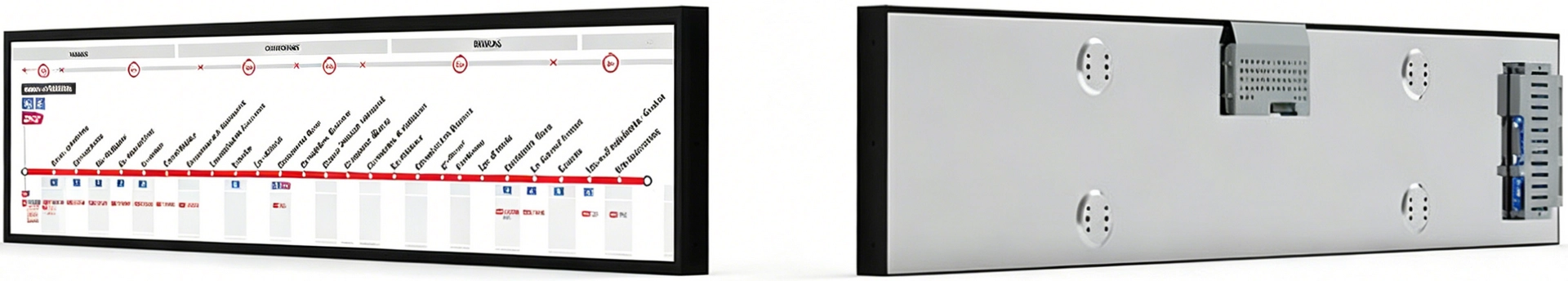
💡 Quick Answers — Stretched LCD Displays for Rail
Why stretched LCD instead of standard 16:9 for rail PID?
Rail infrastructure is built around narrow horizontal spaces — platform edge strips, carriage ceilings, and entrance totems — all 150–200mm tall but 800–2,000mm wide. A standard 16:9 panel is the wrong shape. Cropping a 16:9 panel wastes 60–80% of the backlight as heat behind the bezel. A native stretched LCD sizes the backlight to the active area only — shallower chassis (25–35mm), no wasted power, no thermal hotspots.How does RisingStar prevent vibration damage in stretched rail displays?
Four countermeasures at the component level: screw-lock connectors on all external I/O, through-hole PCB mounting (not surface-mount), thread-locking compound on every chassis fastener, and EPDM vibration-dampening gaskets at the panel-to-enclosure interface. These are standard on every transit-qualified unit — not optional add-ons.What brightness does a stretched rail display need?
Underground platforms: 500–1,000 nits. Semi-outdoor covered platforms and glass concourses: 1,500–2,500 nits. Fully outdoor entrance totems and open-air platform ends: 2,500–5,000 nits with Hi-Tni panels (≥110°C clearing point) and optical bonding.What certifications apply to stretched displays in rail?
Station-side: EN 12966 (visual performance), ADA (accessibility), IK10 impact resistance. Onboard: EN 50155 (electronic equipment for rolling stock), EN 61373 (vibration and shock), EN 50121-3-2 (EMC), EN 45545 (fire safety).How does local dimming save energy on rail PIS displays?
Rail PIS content uses dark backgrounds with white text — the dark area occupies 60–80% of the screen. Local dimming turns off the backlight zones behind the dark area, cutting power by 20–40% and extending LCD lifespan by 30%+ compared to constant-backlight operation.
Stretched vs. Standard: Three Structural Advantages for Rail
1. Space Efficiency — Fitting the Cutout That 16:9 Cannot
Rail infrastructure is built around narrow horizontal spaces. Platform edge strips, overhead canopy mounts, carriage ceiling panels, and entrance totems all share the same dimensional constraint: wide (800–2000mm) but shallow (150–200mm tall). A standard 16:9 monitor is the wrong shape for every one of these positions.
The conventional workaround — masking a 16:9 panel with a bezel to force it into a narrow cutout — carries three penalties:
Wasted backlight power. The full LED backlight array runs behind the entire panel, including the masked zones that nobody sees. In a typical 48" cropped installation, 60–80% of the backlight output illuminates pixels that are hidden behind the bezel. That power dissipated as heat, not light.
Thermal hot spots. Masked LEDs generate heat in a confined area with no airflow. Over months, the thermal gradient between the masked edges and the active center accelerates LED degradation and can push the LCD past its clearing point — the temperature at which the liquid crystal loses its ordered structure and the panel permanently darkens.
Deeper enclosure. A cropped panel requires a chassis 40–60mm deep to accommodate the full backlight module. A native stretched panel, where the backlight is precisely sized to the active area, fits in 25–35mm — critical for carriage ceiling installations where every millimeter of depth reduces passenger headroom.
A native stretched LCD display solves all three. The backlight is sized for the visible area only. Every LED contributes to the displayed image. The chassis is shallower, cooler, and mechanically simpler.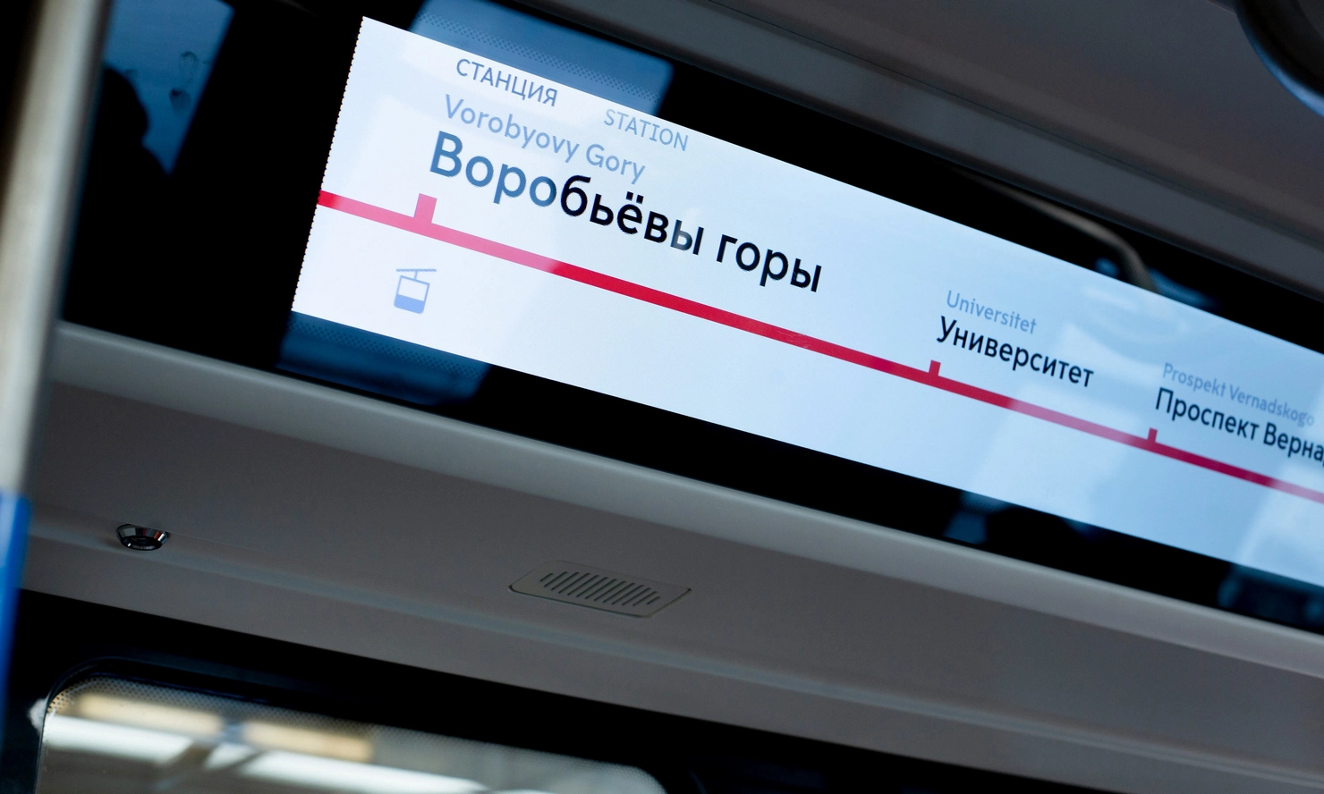
| Metric | Native Stretched LCD | Cropped 16:9 |
|---|---|---|
| Active pixels used | 100% | 20–40% |
| Backlight power | Sized for active area | Full power, most blocked |
| Chassis depth | 25–35mm | 40–60mm |
| Thermal profile | Uniform along long axis | Hot spots at masked edges |
| Enclosure cost | Lower — no dead zone to cool | Higher — must reject masked heat |
RisingStar's stretched LCD display solutions for rail PID use native ultra-wide panel cutting from Tier-1 motherglass — every pixel is active, every LED contributes to the image, and the chassis depth fits the tightest carriage ceiling and platform edge cutouts.
2. Mounting Height — Vandal Resistance and Passenger Safety
Stretched displays are narrow. This is not an aesthetic choice — it is a safety requirement in European and North American rail deployments.
Ground-level displays in public stations face two persistent threats: vandalism (impact, scratching, graffiti) and accidental passenger contact (bags, luggage, wheelchair approaches). Both are mitigated by mounting the display higher. But a standard 16:9 panel mounted at a safe height — above 2.2m from platform level per EN 12966 and ADA signage guidelines — becomes unreadable. The tall panel forces the viewer to look up at an extreme angle, and the bottom half of the screen falls outside the comfortable viewing cone.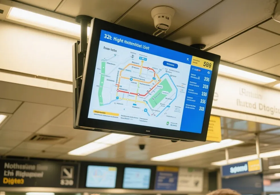
A stretched display solves this geometry. At 90–200mm tall, a stretched panel mounted at 2.2m or higher remains fully within the passenger's natural sightline. The entire content strip is readable without craning — arrival times, route indicators, and service alerts are all visible at a glance. This mounting height simultaneously:
Prevents vandalism. Displays above 2m are outside the reach of casual impact. IK10-rated cover glass provides secondary protection, but the primary defense is simply being out of reach.
Protects passengers. A protruding 16:9 monitor at head height is a physical hazard in crowded platforms. European rail safety assessments treat any protrusion below 2.1m in passenger zones as a risk requiring mitigation. A narrow stretched panel at 25–35mm depth, mounted high, eliminates this hazard entirely.
Meets accessibility codes. ADA and EN 12966 require that informational signage be visible from a standing position at platform level without requiring the viewer to tilt their head more than 30°. Stretched panels mounted at 2.0–2.5m satisfy this by keeping the full content strip within a 10–15° viewing angle from a standing position.
3. Form Factor for In-Carriage Integration
Train and metro carriages have curved interiors. Ceiling cavities are shallow arcs — there is no flat surface wide enough and tall enough for a 16:9 monitor. Side panels above door frames are narrow strips between the door header and the luggage rack.
Stretched LCD displays, with chassis depths of 25–35mm and heights of 90–200mm, fit these curved spaces without modifying the carriage interior. The panel mounts into the existing ceiling channel or door header recess. No structural alteration to the rolling stock. No certification requalification of the carriage body.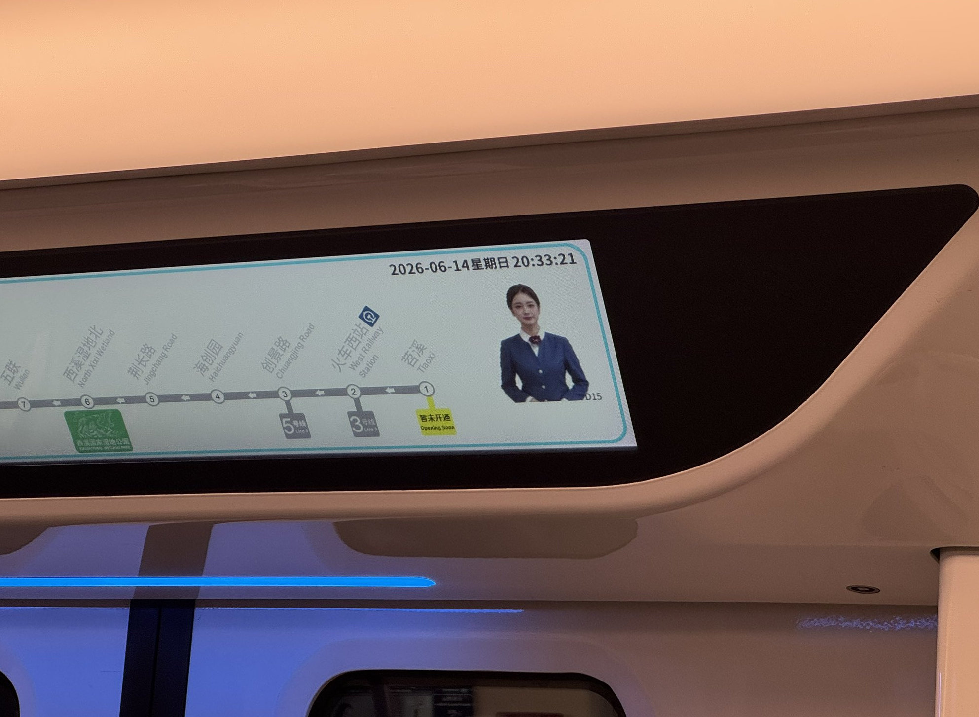
This is why stretched LCD is the default format for onboard passenger information displays across European and Asian metro networks — not because it looks modern, but because it is the only shape that fits.
Deployment Scenarios: Where Stretched LCD Displays Operate in Rail
Platform Edge Strips
The platform edge is the most space-constrained mounting position in any station. The display sits in a narrow channel along the platform edge or under the canopy overhead, with a maximum available height of 150–200mm. A stretched display at 28″–49″ (1920×360 to 3840×540) shows 4–6 train routes simultaneously in a strip 90mm tall.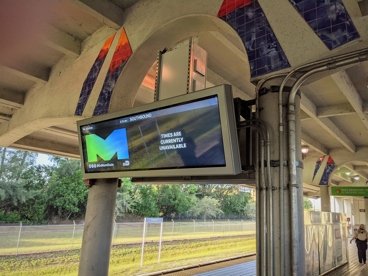
Structural considerations specific to platform edge installations:
Stiffening ribs along the long axis prevent flex in a panel that may be 1200mm wide but only 90mm tall. Mounting points every 200–300mm along the length, not just at the corners.
Aluminum alloy backplates distribute heat along the chassis length. The center of a long stretched panel generates the most backlight heat; without a thermal path to the edges, the center overheats and the LCD clearing point is exceeded.
EPDM vibration-dampening gaskets at the panel-to-enclosure interface absorb the low-frequency shockwaves transmitted through the platform structure by every passing train. These gaskets also seal against moisture ingress.
| Parameter | Covered Platform | Open-Air Platform |
|---|---|---|
| Screen size | 28″–37″ stretch bar | 43″–49″ stretch bar |
| Brightness | 1,000–1,500 nits | 2,500–4,000 nits |
| Resolution | 1920×360 – 1920×540 | 3840×360 – 3840×540 |
| Optical bonding | Recommended | Required |
| Protection | IP54 | IP65/66 |
| Chassis depth | 25–35mm | 30–40mm |
Platform Departure Boards — Overhead Canopy Mount
Station canopy structures provide a natural mounting position for departure boards: a horizontal beam above the platform, typically 2.0–2.5m from platform level. A stretched display mounted here is readable from any position on the platform, protected from ground-level vandalism, and outside the passenger impact zone.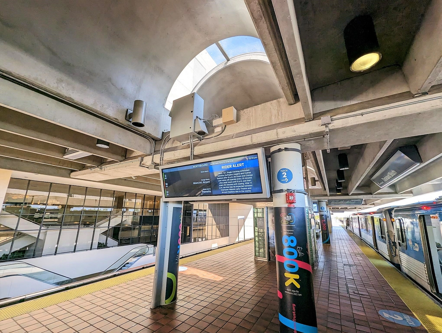
Overhead canopy mounts are semi-outdoor environments. The canopy blocks direct rain but not ambient light — a covered platform at midday still receives 10,000–30,000 lux of indirect and reflected sunlight. Brightness of 1,500–2,500 nits with optical bonding and anti-reflective coating keeps the departure schedule readable under this diffused glare.
At night, ambient light sensors reduce the display to 300–500 nits. This saves power and prevents the display from becoming a visual distraction in the low-light platform environment.
In-Carriage Ceiling and Side Panel Displays
Onboard stretched displays serve two positions inside the carriage:
Ceiling displays — mounted in the central ceiling channel, showing the next-stop indicator, route map, and real-time occupancy status for connecting carriages. Typical format: 28″–37″ stretch bar at 500–1,000 nits. The carriage interior is a controlled lighting environment; high brightness is unnecessary and would cause eye fatigue during a 30-minute ride.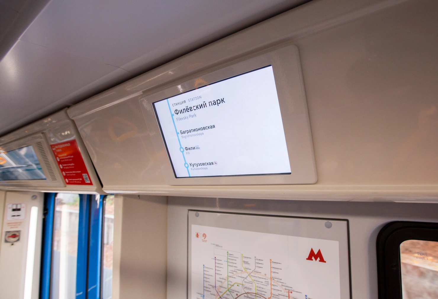
Side panel displays — mounted above each door, showing the next station name and door opening direction. These are the smallest stretched deployments: 3.9″–12″ bar displays at 400–700 nits, sized to fit the narrow header strip between the door frame and the luggage rack.
Both positions require EN 50155 certification for rolling stock electronic equipment. The display must survive vibration, shock, and temperature cycling per the standard's Category 1, Class B or C requirements (depending on the mounting location within the carriage). Operating temperature range for carriage-mounted displays: –20°C to +70°C, with 100+ thermal cycles between minimum and maximum operational temperatures during qualification testing.
Concourse and Hallway Overhead Strips
Large station concourses have wide ceiling spans with no wall surfaces suitable for mounting a standard departure board. Stretched displays mounted overhead — suspended from ceiling rails or embedded in the hallway lighting strip — show route information at a height that keeps them visible without blocking pedestrian flow.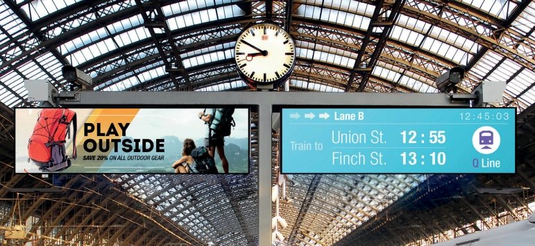
Brightness requirements for concourse overhead strips depend on the hall's lighting environment:
Fully indoor (underground metro concourse): 1,000–1,500 nits, fluorescent lighting at 200–500 lux
Semi-outdoor (glass-roofed or skylit concourse): 1,500–2,500 nits, variable sunlight exposure through glass facades
Transit walkway connecting indoor and outdoor zones: brightness must transition smoothly — ambient light sensors with auto-dimming handle this without manual intervention
Station Entrance Totems
Street-level entrance totems are the most exposed stretched display position. Fully outdoor, facing direct sunlight, rain, and vandalism. The display must operate at 2,500–5,000 nits with IP65/66 sealing and IK10-rated tempered cover glass.
The stretched format is chosen here for the same structural reasons as platform edge strips: the totem's visible face is a narrow vertical rectangle. A 16:9 panel mounted vertically wastes two-thirds of its pixels and backlight. A stretched display fills the totem's face precisely, showing station name, line indicators, and real-time service status.
Vibration Resistance: Component-Level Engineering for Rail Environments
Every passing train transmits low-frequency shockwaves through the station structure. Every kilometre of track travel vibrates the carriage body. Over months of continuous service, this vibration causes three failure modes in standard displays:
Connectors walk loose. Friction-fit HDMI, USB, and DC power connectors lose signal integrity after approximately 20,000 train pass cycles. A loose HDMI connector produces intermittent frame drops — a departure board that flickers is worse than no departure board at all.
PCB components fatigue at solder joints. Surface-mount connectors crack at the solder joint under sustained low-frequency vibration. The crack propagates silently until the connector separates entirely, causing a hard failure with no warning.
Chassis fasteners back out. M3/M4 screws securing the panel to the enclosure undergo micro-rotation from each vibration cycle. After thousands of cycles, the fastener loosens, the panel shifts within the enclosure, and the seal between the panel and the gasket opens — allowing moisture ingress.
RisingStar's transit-qualified stretched LCD displays address each failure mode at the component level:
| Failure Mode | Countermeasure | Implementation |
|---|---|---|
| Connector walk-out | Locking connectors | Screw-lock HDMI, screw-lock USB Type-B, and locking DC power barrels — mandatory on all transit-qualified units |
| Solder joint fatigue | Through-hole PCB mounting | All controller PCB connectors pass through the board and are soldered on the opposite side, distributing vibration load across the full solder surface rather than a single surface-mount pad |
| Fastener micro-rotation | Thread-locking compound | Loctite or equivalent on all M3/M4 chassis fasteners during assembly |
| Panel-to-enclosure seal breach | EPDM vibration-dampening gaskets | Dual-function gaskets at the panel-to-enclosure interface: absorb vibration energy and maintain the moisture seal under dynamic load |
These countermeasures are not optional add-ons — they are standard on every RisingStar stretched LCD display shipped for rail deployment. They are also the basis for meeting EN 50155 vibration and shock requirements (Category 1, Class B/C per EN 61373), which mandate functional random vibration testing at 5–200 Hz with sustained acceleration, followed by simulated shock pulses at peak amplitudes up to 30g.
The qualification process: a sample unit is mounted on a vibration test rig at the specified acceleration spectrum for the target EN 61373 category. The display runs content throughout the test. After the vibration sequence, the unit undergoes shock pulses at the required peak amplitude. Functional performance is verified at each stage — no frame drops, no connector displacement, no backlight flicker, no panel shift within the chassis.
Passenger Safety and Mounting Standards: EU and US Requirements
Stretched LCD displays in rail environments must comply with a framework of safety, accessibility, and impact-resistance standards that govern mounting height, protrusion limits, and physical protection. These requirements differ between station-side and onboard installations, but share a common principle: the display must not present a physical hazard to passengers, and the information it displays must be readable by all users including those with disabilities.
Station-Side Standards
EN 12966 (Variable Message Signs) — European standard governing the visual performance of dynamic signage in transport environments. Key requirements for rail:
Character height must be sufficient for readability at the maximum viewing distance. For a platform edge strip mounted at 2.5m, viewed from 15m down the platform, the minimum character height is approximately 45mm — well within the capability of a 28″–37″ stretch bar at 1920×540 resolution.
Luminance intensity classes (L1–L4) define the required brightness range. Semi-outdoor rail installations typically require L2 or L3 performance — meaning the display must maintain rated brightness under ambient light levels up to 40,000 lux without washout.
Viewing angle performance must support the full range of passenger positions on the platform. IPS panels with 178° horizontal and vertical viewing angles are specified to ensure the departure time is readable whether the passenger is standing directly below or 20 meters to the side.
ADA (Americans with Disabilities Act) — Applies to US transit installations. Key requirements:
Protrusion limits (the "4-inch rule"). ADA §307.2 limits wall-mounted objects to a maximum protrusion of 4 inches (100mm) when the leading edge is between 27″ (686mm) and 80″ (2032mm) above the finished floor. This is a hard constraint for platform-level and concourse displays. A standard 16:9 monitor in a plastic housing typically exceeds 100mm depth — violating the rule and requiring either a recessed mounting cavity (expensive structural work) or a cane-detectable barrier below the display (clutters the platform). A native stretched LCD at 25–35mm chassis depth clears the 4-inch limit with room to spare — no recessed cavity, no barrier, fully ADA-compliant out of the box.
Mounting height for informational signage: between 40″ (1016mm) and 70″ (1778mm) above finished floor for tactile access, or higher for visual-only displays provided the content remains readable at the maximum viewing angle. Stretched displays mounted at 2.0–2.5m with content visible at a 15° downward viewing angle satisfy this requirement.
Luminance contrast ratio ≥ 3:1 between text and background. Dark-background stretched displays with white text at 1,500+ nits easily exceed this threshold. Local dimming further enhances perceived contrast by eliminating backlight bleed in the dark zones.
Audio output for screen reader compatibility on interactive displays. The open frame display's customizable connector layout allows integrators to route audio to external speakers.
Impact resistance — All ground-level or near-ground displays in public rail stations require IK10-rated tempered glass (20-joule impact resistance). For stretched displays mounted above 2.2m, IK08 is typically sufficient, though many transit authorities specify IK10 as standard regardless of height to account for thrown objects.
Onboard Standards
EN 50155 — The primary standard for electronic equipment installed on rolling stock. It covers:
Operating temperature: –20°C to +70°C (with –40°C option for arctic or alpine deployments), tested across 100+ thermal cycles
Vibration and shock: Per EN 61373, Category 1 (body-mounted), Class B or C depending on specific mounting location
EMC: Per EN 50121-3-2, the display must not emit electromagnetic interference that affects signalling or communication systems, and must be immune to the electromagnetic environment of the carriage
Power supply: Wide input voltage range (typically 24V, 36V, 48V, 72V, or 110V DC) with surge and reverse-polarity protection
Fire and smoke: Materials must meet EN 45545 fire safety standards for railway vehicles — low smoke, low toxicity, limited flame spread
EN 45545 (Railway Fire Protection) — All display enclosure materials, cables, and cover glass must meet the fire classification for the installation zone. For passenger cabin equipment, HL2 or HL3 hazard level classification applies depending on the rail network's fire safety category.
Semi-Outdoor Brightness and Temperature Specifications
Most stretched LCD displays in rail stations operate in semi-outdoor environments — covered platforms, glass-roofed concourses, and transition zones between indoor and outdoor spaces. These environments are more demanding than fully indoor installations and less predictable than fully outdoor ones. The display must handle:
Variable ambient light. A covered platform at noon receives 10,000–30,000 lux of indirect sunlight through the canopy opening. The same platform at dusk receives 100 lux from overhead fluorescent fixtures. The display must be readable in both conditions without manual brightness adjustment.
Temperature swings. Semi-outdoor stations are not climate-controlled. Summer solar loading pushes canopy temperatures to 50–60°C. Winter cold drops the platform to –10°C or below in northern latitudes. The display must start reliably at both extremes and operate continuously without thermal throttling.
Condensation. The temperature differential between the display surface and the ambient air causes condensation on the cover glass during morning warm-up and evening cool-down. Optical bonding eliminates the internal air gap where condensation forms; external condensation is managed by hydrophobic coatings.
Brightness Selection by Installation Zone
| Zone | Location | Ambient Light | Recommended Brightness | Panel Technology |
|---|---|---|---|---|
| A — Fully indoor | Underground platforms, mezzanines, ticket halls | 200–500 lux | 500–1,000 nits | Standard IPS |
| B — Semi-outdoor | Covered platforms, glass concourses, skybridge walkways | Variable, sun-exposed part of day | 1,500–2,500 nits | IPS + anti-glare coating + optical bonding |
| C — Fully outdoor | Station entrances, open-air platform ends, street totems | 100,000+ lux direct sun | 2,500–5,000 nits | Hi-Tni (≥110°C clearing point) + optical bonding + AR coating |
Temperature Management
Semi-outdoor and outdoor stretched displays must maintain stable operation across –20°C to +70°C. Two temperature-related failure modes must be prevented:
High-temperature panel blackening. Standard LCD panels use liquid crystal materials with a clearing point of 70–80°C. When the panel temperature exceeds this threshold, the liquid crystal loses its ordered structure and the display permanently darkens. Hi-Tni (high-temperature resistant) panels use liquid crystal with a clearing point of ≥110°C, providing a 30–40°C safety margin above the maximum operating temperature. This is not optional for outdoor and semi-outdoor rail deployments — it is a prerequisite.
Low-temperature cold start. Below 0°C, standard LCD response times increase dramatically — the liquid crystal becomes viscous and the display shows severe ghosting. Integrated PTC (positive temperature coefficient) heating elements warm the panel during cold starts, reducing the liquid crystal to operating viscosity within minutes. Without PTC heaters, a stretched display mounted on an exposed platform in winter may take 15–30 minutes to reach acceptable response times — unacceptable for a real-time departure board.
Optical Bonding and Anti-Reflective Treatment
Semi-outdoor environments demand optical bonding and AR/AG surface treatment on stretched LCD displays. The reasons:
Optical bonding laminates the cover glass directly to the LCD panel, eliminating the internal air gap. Without bonding, the air gap reflects approximately 4% of incident light at each glass-air interface — creating a mirror effect under bright ambient light that makes the display unreadable. Bonding reduces internal reflections to below 1%, restoring contrast and readability.
Anti-reflective (AR) coating on the outer glass surface reduces specular glare from direct and reflected light sources. Premium AR coatings achieve >93% light transmissivity with <2% surface reflectivity.
Anti-glare (AG) finish diffuses surface reflections across the glass surface, preventing the bright reflection spots that make a display unreadable from certain angles. AG treatment must be balanced against resolution clarity — too aggressive a diffusion reduces sharpness. Rail applications typically use a medium AG finish (gloss 80–120 GU) that preserves readability at typical platform viewing distances of 2–15 meters.
Dark Backgrounds and Local Dimming: The Energy and Lifespan Advantage
Rail passenger information displays share a common content design pattern: dark background, light text. A typical departure board shows 4–6 route entries as white text on a black or dark blue field, with the background occupying 60–80% of the screen area at any given moment. This is not an arbitrary design choice — dark backgrounds provide maximum contrast under the variable lighting conditions of semi-outdoor stations, and they are the standard visual language for transit information systems worldwide (per EN 12966 legibility requirements).
On a traditional LCD with a constant backlight, the dark background is an illusion. The full LED backlight array runs at rated power regardless of content. The LCD pixels block the light in dark zones, but the backlight still consumes full power and generates full heat. The dark pixels do not save energy — they waste it. A 2,000-nit stretched display showing a departure board with 75% dark background still draws the same power as if it were showing a full-screen white image.
Local dimming changes this equation fundamentally.
How Local Dimming Works on Stretched LCD Displays
Local dimming divides the LED backlight into independently controlled zones — typically 100–500+ zones depending on the panel size and Mini-LED density. A real-time content analysis algorithm maps each video frame to the backlight zone layout. Zones behind bright content (text, route indicators) are driven at full brightness. Zones behind dark content are dimmed or turned off entirely.
For rail PIS content with its characteristic dark background and sparse white text, the impact is substantial:
Backlight power reduction of 20–40% compared to constant-backlight operation at the same peak brightness. Only the zones behind the active text are fully illuminated. The remaining 60–80% of the backlight — behind the dark background — draws minimal or zero power.
Overall system power reduction up to 50% when combined with ambient light sensors that reduce brightness during low-ambient periods (nighttime, underground stations). A traditional 55" outdoor high-brightness display can consume over 3,000 kWh annually. With local dimming, the same display draws 20–40% less on average, depending on content dark ratio.
Extended LCD lifespan by 30% or more. Heat is the primary degradation mechanism for LED backlights and LCD panels. By dimming or extinguishing LEDs in dark zones, local dimming reduces the overall thermal load. Cooler LEDs degrade slower. Cooler driver ICs last longer. The net effect: the display reaches its L70 threshold (brightness at 70% of initial value) significantly later than a constant-backlight equivalent.
Why Local Dimming Is Particularly Effective on Stretched Rail Displays
Stretched displays in rail have two characteristics that amplify the local dimming advantage:
High dark-to-bright ratio. A typical rail PIS display shows 4–6 lines of route information on a predominantly dark field. The active text area occupies 20–40% of the screen. This means 60–80% of the backlight zones can be dimmed or turned off — far more than on a general-purpose display showing mixed content (advertising, video, images) where the dark ratio might be only 20–30%.
24/7 operation. The energy savings compound over continuous operation. A 30% power reduction on a display that runs 24 hours per day, 365 days per year, translates to a meaningful reduction in operating cost — and in the thermal stress that drives component aging. For a metro network with 100+ stretched displays, the cumulative energy and maintenance savings are significant.
Contrast and Readability Benefits
Local dimming does not only save energy. It also improves display performance:
Contrast ratio enhancement. With local dimming, dark zones achieve near-zero backlight emission, producing true deep blacks instead of the "dark gray" of constant-backlight LCDs. Contrast ratios of 1,000,000:1 are achievable — compared to 1,000:1–3,000:1 on traditional constant-backlight IPS or VA panels. Higher contrast means the departure time text stands out more sharply against the background, improving readability under the variable lighting conditions of semi-outdoor platforms.
Halo suppression. A concern with local dimming is blooming — bright text bleeding into the adjacent dark zone, creating a halo. Advanced local dimming algorithms combined with dual-layer precision diffusers suppress this halo effect, maintaining clean separation between text and background. On a stretched display where the text lines are vertically separated by dark gaps, proper halo suppression ensures each route entry is independently crisp.
Dynamic content response. When the PIS switches from a static departure board to a full-screen emergency alert (red background, white text), local dimming instantly shifts from zone-dimmed to full-backlight mode. The transition is seamless and frame-accurate — no delay, no visible step. When the emergency clears and the display returns to the normal departure board, the backlight returns to zone-dimmed operation automatically.
RisingStar Stretched LCD Display Solutions for Rail
RisingStar manufactures stretched LCD displays for rail and transit applications in a 4,000 m² ISO 9001-certified facility in Shenzhen with Class 10,000 cleanroom assembly. As an open frame display manufacturer since 2009, we produce every panel — from standard 16:9 to custom stretch bar — under the same roof, with the same quality control. Grade A/A+ panels are sourced directly from LG Display, AUO, BOE, Innolux, and Tianma — the motherglass is cut and re-driven at the mask stage to produce native ultra-wide panels with the same brightness, lifespan, and color uniformity as standard-format panels from the same production line.
Our stretch bar high-brightness TFT LCD panel product line covers the full range of rail PID deployments — from 3.9″ carriage side panels to 65″ entrance totem displays — with custom aspect ratios, brightness up to 5,000 nits, and local dimming configured to your PIS content layout.
Every unit undergoes 100% factory inspection, AOI pixel scanning, luminance uniformity measurement, and a 72-hour burn-in at 50°C before shipment. 3–5 year model availability commitments with stable mechanical dimensions and electrical pinouts protect rail projects from the EOL disruption that consumer-grade monitors introduce.
Capability Summary
| Capability | RisingStar Specification |
|---|---|
| Screen sizes | 7″–65″ stretch bar, custom aspect ratios |
| Brightness | 500–5,000 nits, factory-calibrated to deployment zone |
| Panel technology | Hi-Tni liquid crystal (≥110°C clearing point), IPS |
| Local dimming | Mini-LED FALD with 100–500+ zones, real-time content analysis |
| Touch integration | PCAP with glove mode / wet-hand, custom sensor for ultra-wide format |
| Optical bonding | OCA sheet lamination and OCR liquid-resin processes |
| Surface treatment | AR coating (>93% transmissivity, <2% reflectivity) + AG finish |
| Protection | IP65/66 front-panel sealing, IK08–IK10 cover glass |
| Vibration countermeasures | Locking connectors, through-hole PCB, Loctite fasteners, EPDM gaskets |
| Interfaces | LVDS, eDP, HDMI — screw-lock variants standard on transit units |
| Temperature range | –20°C to +70°C (–40°C option with PTC heaters) |
| Certifications | CE, RoHS, REACH; EN 50155 / EN 50121 / EN 45545 support |
| Supply stability | 3–5 year model availability commitment |
Project Process
Step 1 — Requirement specification. Provide deployment zone (A/B/C), target brightness, resolution, interface, touch requirements, and environmental conditions. Include tender-specific certification requirements upfront.
Step 2 — Engineering review. Our engineering team validates mounting dimensions, structural rigidity calculations for the target panel length, thermal path design along the long axis, and the certification path for your target market. Response within 8 hours.
Step 3 — Sample production. A custom sample built to your specification is tested and shipped within 10 working days. Every prototype undergoes 100% inspection, luminance uniformity measurement, and a 72-hour burn-in at 50°C.
Step 4 — Qualification and certification. You evaluate the sample against mechanical and electrical specifications. We provide all test data required for your tender submission — brightness reports, IP/IK certificates, vibration and shock test results per EN 61373, and EN 50155 compliance documentation.
Step 5 — Volume production. Production runs with consistent quality across batches, 15–25 working day lead time. Batch-to-batch traceability maintained throughout.
Step 6 — Ongoing support. 24/7 technical support, firmware updates, local dimming algorithm tuning for your specific PIS content layout, and after-sales service. Standard 2-year warranty, extendable to 3 years for large-scale rail deployments.
📧 ai@risinglcd.com · 💬 +86 158 8946 9208 · 🌐 www.risinglcd.com

